Product description
-
This device is a chronothermostat with electronic temperature control and daily electromechanical clock. Produced in accordance with the applicable EC directives, according to the standards EN 60730-2-9, EN 60730-2-7, it is entirely manufactured in Italy.
WARNING! It is recommended to install the device in strict accordance with the safety regulations and laws in force. Before making any connection, make sure that the main switch is off.
Technical specifications
-
Power supply 2x1.5V LR6 Alkaline Batteries (Type AA)
Battery life > 1 year
Maximum capacity of the contacts 5A(1A) 250VAC
Type of action 1B
Class ErP I (+1%) - 811/2013 (regolazione ON/OFF) - ErP IV (+2%) - 811/2013 (regolazione TPI)
Temperature probe NTC 100KΩ@25°C
Temperature differential on regulation regolazione ON/OFF: 0,5K
Degree of protection IP20
Insulation class Tipo II (doppio isolamento)
Pollution degree 2
Software class A
Heat and fire resistance Category D
Storage temperature -25÷60°C
Rated impulse withstand voltage 2,5kV
Installation wall
COMFORT temperature regulation range 10°C÷30°C
REDUCED temperature regulation range 10°C÷26°C
Minimum settable interval 15 minuti
Installation
-
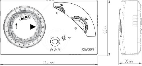
Install the device away from heat sources and and drafts, about 1.5m from the floor.
Using a screwdriver open the device via the side hooks on the left and then remove the front, separating it from the base (Fig.2).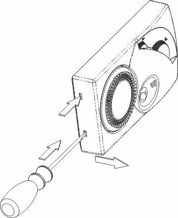
Fig. 2 Remove the screw and detach the terminal cover (Fig.3 A).
Insert the cables through the opening on the bottom (Fig.3 C).
Attach the base to the wall or on the flush mounted box with screws, using the relevant holes (Fig.3 B). To facilitate the electrical connections, remove the 3-way terminal block (Fig.3 D), exerting slight outward pressure on the lever that secures the terminal block to the base (Fig.3 E).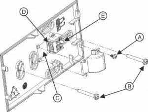
Fig. 3 Connect the wires to the terminal block as indicated (Fig.4).
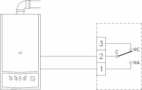
Fig. 4 After connecting the cables, insert the terminal block into place, pressing it gently until the lever clicks. Replace the terminal cover, screwing it back onto the base (Fig.3 A).
Select the temperature regulation mode, as described in the chapter “REGULATION TYPE”.
Insert the batteries into the slot inside the front ensuring correct polarity (Fig.5).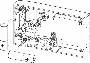
Fig. 5 Refit the front onto the base, tilting it 45° and engage the notches (Fig.6).
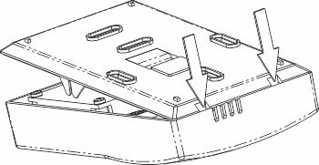
Fig. 6 Close the device again, aligning the contacts with the terminal block on the base until the upper part touches the lock hooks (Fig.7 A) .
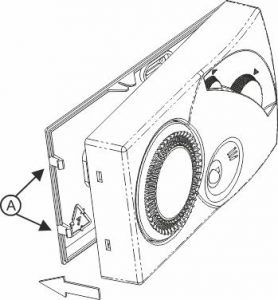
Fig. 7 Press lightly to facilitate connection of the two parts.
BATTERY REPLACEMENT
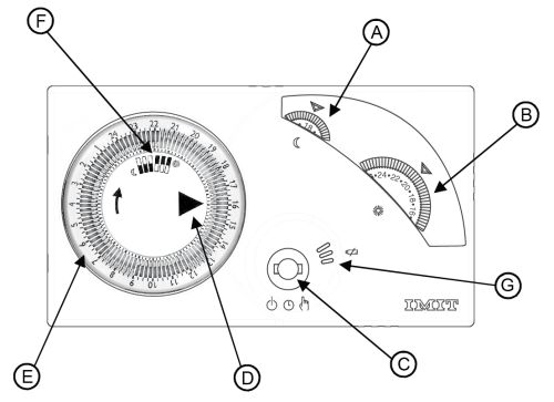
Fig. 1 Replace the batteries when the red light flashes (Fig.1 G) .
Using a screwdriver open the device via the side hooks on the left and then remove the front, separating it from the base (Fig.2) and replace the batteries as indicated (Fig.5).
Fig. 2 Fig. 5 Close the device again as shown in the installation instructions.
Description of controls and operation
-
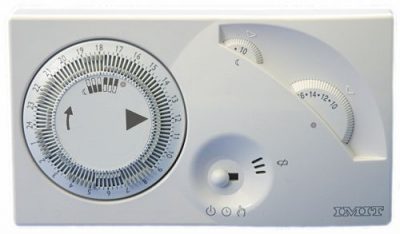
COMMANDS LEGEND (Fig.1)
A = Reduced temperature setting knob

B = Comfort temperature setting knob
C = Operating mode selector
D = Timer index
E = Programmer clock
F = Position of selectors for Comfort/Reduced temperature G = Light for low battery warning and alarmsCLOCK ADJUSTMENT
Rotate the disc of the clock clockwise positioning the indicator
on the current time (Fig.1 D). Remember to reset the clock moving from Daylight Saving Time to Standard Time and vice versa.MODO OFF
Position the selector (Fig.1 C) on
 to turn off the thermostat.
In case of ambient temperature < 5°C the anti-freeze function is activated.MANUAL OPERATION
Position the selector (Fig.1 C) on the symbol

The reduced temperature knob (Fig.1 A) Fig.1 A) and the clock (Fig.1 E) are disabled.
Set the desired temperature: position the desired value under the reference indicator by turning the Comfort knob(Fig.1 B).AUTOMATIC OPERATION
The temperature regulated in the environment (set with the Comfort or Reduced knobs) depends on the settings chosen on the clock and changes automatically.
Position the selector (Fig.1 C) on the symbol
Set the comfort temperature: position the desired value under the reference indicator by turning the Comfort knob(Fig.1 B).
Set the reduced temperature: position the desired value under the reference indicator by turning the reduced temperature knob (Fig.1 A).
Program the clock by positioning the levers (Fig.1 F):- outwards for the comfort temperature ;
- towards the centre for reduced temperature
Check that the index of the clock shows the current time and if necessary proceed as indicated in chapter “CLOCK ADJUSTMENT”.
REGULATION TYPE (Reserved for installers)
The position of the jumpers A and B (Fig.8) allows the device to work with two different types of temperature regulation:
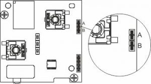
Fig. 8 - ON / OFF (factory setting): The device is activated when the ambient temperature is lower than the temperature set and turns off when it reaches the temperature set.
A=Present, B= Present - TPI: The device is activated when the ambient temperature is lower than the temperature set and, approaching the required temperature, reduces the operating periods of the boiler, optimising environmental comfort and reducing energy consumption.
A=Absent, B=Present (optimised for radiator systems) A=Absent, B=Absent (optimised for floor systems)IMPORTANT: repositioning of the jumpers must be performed before inserting the batteries or in any case with the device with batteries removed.
- outwards for the comfort temperature
Problem solving
-
Problem
The red light of the device (Fig.1 G) is activated to indicate:
Possible cause- with 2 slow flashes: batteries almost flat.
- with 2 quick flashes: batteries flat.
- with continuous quick flashing: fault inside the device.
Solution- Replace them as soon as possible.
- Replace them to restore functioning of the device.
- Replace the batteries and check the operating environment conditions before replacing the device.