Product description
-
This product is manufactured in accordance with standards EN 60730-2-9, EN 60730-2-7, ETSI EN 301 489-1 (DPT R, DPT VR), ETSI EN 300 200-2 (DPT R, DPT VR), in accordance with applicable EC directives and it is entirely manufactured in Italy.
WARNING! It is recommended to install the device in strict accordance with the safety regulations and laws in force. Before making any connection, make sure that the main switch is off.
Technical specifications
-
Power supply Batteries (2x1,5V) - Output: relay ON-OFF - 2x1.5V LR03 Alkaline batteries (AAA type)
Battery life > 1 year
Maximum capacity of the contacts 5A(1A) 250VAC
Type of action 1B
Class ErP I (+1%) - EU 811/2013
Maximun ambient temperature 50°C
Temperature display range 0°C÷39°C
Temperature regulation range 5°C÷35°C
Temperature resolution 0.1°C
Temperature probe NTC 100KΩ@25°C
Temperature differential from 0.1°C to 2.0°C (standard 0.2°C)
Degree of protection IP20
Insulation class Type II (double insulation)
Pollution degree 2
Software class A
Heat and fire resistance Category D
Storage temperature -25÷60°C
Rated impulse withstand voltage 2,5kV
Installation wall-mounting
Installation
-
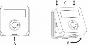
Fig. 1 Install the device away from heat sources and drafts, about 1.5m from the floor.
Open the device by pressing the small tab on the underside of the base (Fig.1 A). Turn the front panel upwards (Fig.1 B) and lift it slightly to release it (Fig.1 C).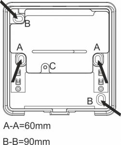
Fig. 2 Remove the internal protection covering the terminals by unscrewing the screw (Fig.2 C) and turning the cover upwards. Attach the base to the wall, using the horizontal (Fig.2 A-A) or diagonal distance (Fig.2 B-B).
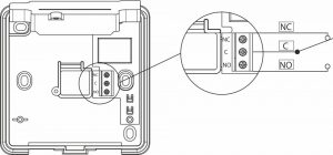
Fig. 4 Insert the cables through the opening at the bottom and connect them to the terminal board (Fig.4) then replace the internal cover and tighten the screw (Fig.2 C).
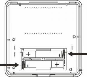
Fig. 3 Insert the batteries in the front panel (Fig.3).
To close the device, proceed as before but reversing the sequence of operations: match the upper sides of the two parts (Fig.1 C) then turn the front panel downwards (Fig.1 B) until the lower hook clicks (Fig.1 A) on the base.
Replacing the batteries
When the
 symbol flashes (batteries low) it is necessary to replace them. Proceed as indicated in the installation instructions (Fig. 1 and Fig.3). Put the cover back on the base before performing any operation.
 Description of controls and operation
-
The controls consist of a ring with four positions identified by the arrows


 with a central button OK. Press the ring in correspondence with the arrow to activate one button at a time. Press the OK button in the centre. Use the arrow buttons to change the time and temperature values or to select the options, the central OK button usually confirms the settings.
First start-up (Fig.5)

Fig. 5 Set the clock
- Set the format 24H or 12H using , then OK.
- Set the hour using , then OK.
- Set the minutes using , then OK.
OFF and the clock appear on the display.
OFF mode (Fig. 6)

Fig. 6 The antifreeze function is active. Press for 3 seconds:
to set the clock (as above).
to set the season mode Summer/Winter (standard: WINTER).
to go from OFF to ON and vice versa.Press OK for 10 seconds to enter the Installer Menu.
Active modes
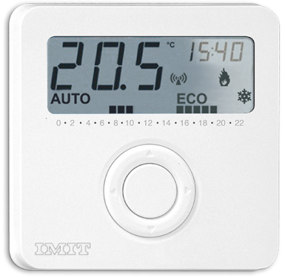
Ambient temperature is always in the foreground.
Press OK to show the clock or the set-point temperature in the upper right corner.Press
to select AUTO, MAN, MAN ECO modes (standard: AUTO).Manual and Manual Eco (Fig. 7)

Fig. 7 Press
or to change and save the temperature set-points.
MAN = comfort temperature (standard: WINTER = 20,0°C / SUMMER = 25,0°C). MAN ECO = economy temperature (standard: WINTER = 16,0°C / SUMMER = 28,0°C).Automatic mode (Fig. 8)
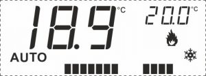
Fig. 8 The display shows in its lower part:
 hours set at Comfort temperature (t1).
 hours set at Economy temperature (t2).
The set-point temperature (t1 or t2) depends on the saved time program and changes automatically.
Time program
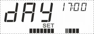
Fig. 10 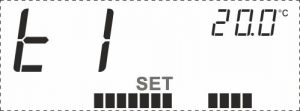
Fig. 11 Hold 3 seconds, the current time of day appears in the upper righ corner (Fig.10):
SET and the symbol related to the current time flash.
Select the desired temperature per every hour along the day.
Press to set t1 temperature.
Press to set t2 temperature.
Press to move along the hours without changing the settings. Press OK to confirm the program settings.The display shows t1 (Comfort) temperature first and t2 (Economy) soon after (Fig.11).
Change t1 (Comfort) by then OK
(standard: WINTER = 20,0°C / SUMMER = 25,0°C).
Change t2 (Economy) by then OK
(standard: WINTER = 16,0°C / SUMMER = 28,0°C).Winter mode

The Comfort temperature is higher than the Economy temperature (t1>t2). When Tamb < Tset (Room temperature < Set temperature), the heating is activated
 .
.Summer mode

The Comfort temperature is lower than the Economy temperature (t1<t2). When Tamb > Tset (Room temperature > Set temperature), the cooling is activated
 .
.Installer menu (Fig. 12)

Fig. 12 On OFF mode, press OK for 10 seconds to enter the Installer Menu. Press
to select the options;
Press to change the values;- AF = Antifreeze threshold (standard 6.0°C);
- HYS = Temperature differential (standard 0.2°C);
- OFS = Temperature offset correction (standard 0.0°C);
- °C = Select degrees Celsius/Fahrenheit (standard Celsius);
- rAd = (only DPT R , DPT VR). Press to select YES and confirm by pressing again. At the end of the pairing procedure, “rdY” will appear on the display if it was successful, “Err” if it was unsuccessful;
- CLR = Press to select YES and confirm by pressing again. Wait 4 seconds for the automatic reset. Reset factory values.
Press OK to exit the installer menu.
- Set the format 24H or 12H using