Product description
-
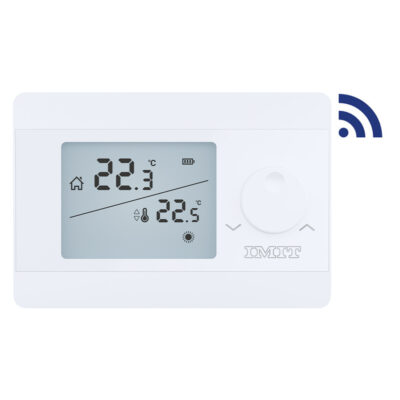
Silver TA/RF S is a digital radio room thermostat with TPI algorithm, ideal for regulating heating or cooling. The backlit LCD display clearly shows the detected room temperature, set temperature, active operating mode, status icons and flat battery warning. The external knob makes temperature regulation even more immediate. Includes the Antifreeze function and allows temperature calibration with a range of ±8°C.
- Precise temperature measurement
- Battery powered (included in the package)
- ON/OFF control
- Heating/cooling calibration
- Radio connection to the boiler
- Heating/cooling mode
- TPI algorithm
- Precise temperature measurement
DECLARATION OF CONFORMITY
Compatible Directives:
Radio and Telecommunications Terminal Equipment Regulation 2014/53/EU (R&TTE/RED EN 301 489-1 V2.1.1:2017, EN 300 220-1V3.1.1:2017, EN 301 489-3 V2.1.1:2017, EN 300 220-2 V3.1.1:2017, EN 62479: 2010)
Electromagnetic Compatibility Regulation 2014/30/EU (EN 61000-6-3: 2021, EN 61000-6-1: 2019)
Low Voltage Directive 2014/35/EU (EN IEC 60730-2-9:2019/A2:2020, IEC 60730-1:2013/AMD2:2020)TECHNICAL SPECIFICATIONS
Room Thermostat
Dimensions: 85mm/125mm/24mm
Operating Current: 3V DC (2 x AAA alkaline battery)
Temperature Measurement Accuracy: 0,1°C
Operating Sensitivity: 0,5°C
Operating Temperature Range: 5°÷30°C
Battery Life: 1 Year (2 x AAA)
Operating Temperature: -10°÷50°C
Storage Temperature: -20°÷60°CReceiver
Dimensions: 90 mm / 90 mm / 25 mm
Operation Current: 230V AC
Relay NO Switching Current:
7A (240VAC – Resistive Load)
10A (120VAC – Resistive Load)
Storage Temperature: -20°÷60°CCONTROLS AND DISPLAY LEGEND
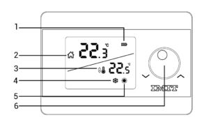
1 – Battery Indicator
2 – Room Temperature
3 – Set Temperature
4 – Cooling Indicator
– If the Cooling Indicator is blinking, the cooling unit is working.
– If the Cooling Indicator is steady, the cooling unit is not working.
5 – Heating Indicator
– If the Heating Indicator is blinking, the heating unit is working.
– If the Heating Indicator is steady, the heating unit is not working.
6 – ON/OFF and Temperature Setting ButtonLegend of the receiver
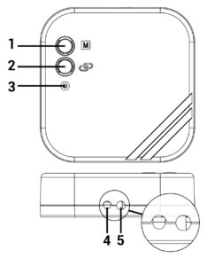
1 – Manual Operation Button:Deactivates the Receiver and allows you to use heating/cooling unit manually.
2 – Pairing Button:Pairs the Receiver and the Room Thermostat.
3 – Receiver LED Light
4 – Receiver Power Cable Input
5 – Heating/Cooling Unit ConnectionCable InputRECEIVER LED DESCRIPTIONS
Constant Red – Receiver has power but Receiver and Room Thermostat are not paired.
Blinking Green – Waiting for pairing signal from the Room Thermostat.
Constant Green – Receiver and Room Thermostat are paired. Heating/cooling unit is not operating.
3 Short Orange Blinking – Operate the heating/cooling unit signal has reached to the Receiver.
Constant Orange – Heating/cooling unit is operating.
3 Short GreenBlinking – Shut the heating/cooling unit down signal has reached to the Receiver.
Blinking Orange – Heating/Cooling unit operates in manual mode.
Blinking Red – Receiver did not get any signal from the Room Thermostat for 22 minutes or longer. Heating/cooling unit has shut down.It is recommended to install the thermostat scrupulously complying with the safety standards and legal provisions in force. Before making any connections, make sure that the main switch has been turned off.
Technical specifications
-
Installation
-
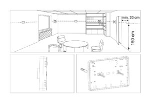
ROOM THERMOSTAT PLACEMENT
Room Thermostat needs to be placed in the room which is used most frequently. For instance; living room or lounge. Placing the Room Thermostat in a spot that have air circulation like entrance of a room or side of window should be avoided. Also anywhere close to heating/cooling units such as radiator, stove and spots which get direct sun lights would not be suitable. Room Thermostat needs to be located above the floor 150 cm height. Few trials may be made to find the most convenient spot.
BATTERY PLACEMENT
Before starting, power off the device connected to the Room Thermostat and make sure that the energy is cut off.
As shown in the picture, press the screwdriver forward from the space shown, bend the tabs and separate the front cover. Insert 2 new AAA alkaline batteries in the battery housing with the correct battery direction. Replace both batteries at the same time. Then align the front part of your Room Thermostat to the back and squeeze it towards the back.
BATTERY REPLACEMENT
When the
 icon appears on the screen, it means “low battery warning”. It is recommended to replace the batteries when this warning appears.
Warning: When the product is not used for a long period (more than 15 days), remove the batteries. Otherwise, malfunctions that may occur would be out of warranty. Please throw your dead batteries into the waste bin for batteries.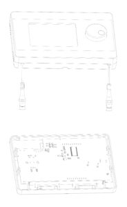
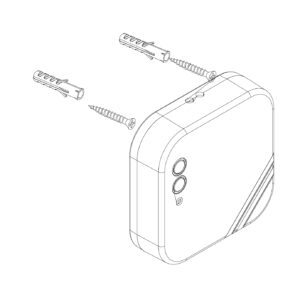
RECEIVER PLACEMENT
The important things to note for the Receiver placement is avoiding physical contact between the Receiver and heating/cooling unit, and protecting it against materials such as liquid, dust etc.
The devices should be placed in order to minimize the damage to the received and transmitted signals by paying attention to the following points;
- The devices should not be mounted on metal surfaces.
- The devices should not be installed close to electrical cables and electronic equipment such as computers and television units.
- The devices should not be installed near large metal structures or other building materials using fine metal meshes such as special glass or special concrete.
- Distance between the Room Thermostat and the Receiver should not exceed 20 meters or 2 floors.
- Receiver must be installed at least 50 cm away from the heating/cooling unit.
RECEIVER SETUP
First, shut down your heating/cooling unit and your heating/cooling unit’s power source with all electrical current (fuse, socket etc.)
As shown in the connection diagram, connect one end of the heating/cooling unit connection cable to the COM and the other to the NO input of the Receiver.
Connect the other ends of the cable -which you connected to the Receiver to room thermostat connection terminal as shown in your heating/cooling unit’s user manual.
You must first connect the Receiver power cable to the Receiver and then to the fuse to which the heating/cooling unit is connected.
After completing the cable connection process, firstly turn on your fuse and then your heating/cooling unit.
By pressing the Receiver’s manual usage button for 2 seconds, you should see the Orange Light blinking on the Receiver. In this way, after making sure that the heating/cooling unit is operating, press the same button again for 2 seconds and see that the Orange LED turns off.
Set up the Room Thermostat to pair the Receiver with the Room Thermostat.
RECEIVER WIRING DIAGRAM HEATING/COOLING UNIT
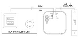
Warning!
Operations within the heating / cooling unit or the electrical installation must be carried out by professionally qualified persons.PAIRING THE ROOM THERMOSTAT AND THE PAIRING THE ROOM THERMOSTAT AND THE RECEIVER
Primarily press the sync button of receiver for 2 seconds and see blinking green light of receiver.
While your device is turned off, press and hold the button for 3 seconds.
Press the button until the “Adr” menu appears.
Then turn up the button to right or left way.
If the pairing is successful, the green flashing LED on the receiver will be constant.
Receiver and Room Thermostat have been paired to each other.
ROOM THERMOSTAT TEMPERATURE CALIBRATION
Temperature sensors which are used in Room Thermostats are highly sensitive. You may need to calibrate your Room Thermostat if you would like to get the same temperature values with other thermometers in your living space. While your device is turned off, press and hold the button for 3 seconds.
Press the button until the “ CAL” menu appers. In order to see the desired temperature, set the temperature difference by turning the button to right or left. This value can be arranged between “-8°C” and “+8°C”.
To save the settings and exit, press the “On/Off” button until the device turns off.
Note: Recommended tempreture calibration is “0.0°C”.
ROOM THERMOSTAT HEATING / COOLING MODES
Your Room Thermostat has heating and cooling modes. In order to switch easily between heating and cooling modes:
While your device is turned off, press and hold the button for 3 seconds.Press the button until the “FUN” menu appears.
You can switch between “ HER” (heating) and “COO” (cooling) modes by turning the button to right or left in the “FUN” menu.
To save the settings and exit, press the button until the device turns off.
The settings you have made have been saved. Once you turned on your device, it will operate with the changed settings.
FACTORY SETTINGS RESET
You can reset your Room Thermostat to its default factory settings. This operation resets the calibration setting and heating/coling modes to factory setting. To reset your Room Thermostat to factory setting:
While your device is turned off, press and hold the button for 3 seconds.
Press the button until the “RST” menu appears.
While in the “RST“ menu, turn the button to right or left in order to select “ YS“ option and press the button.
Your device will be turned off and reset to factory settings.
Description of controls and operation
-
MANUAL MODE
To change the room temperature, turn the knob right or left to set the desired temperature.
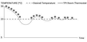
TPI ROOM THERMOSTAT WORKING LOGIC
Your Room Thermostat works with the TPI algorithm. Room Thermostats using TPI technology predict when the temperature of your home will rise above or below the set temperature and turn the heating / cooling unit on and off accordingly. This ensures that your home stays at the temperature you set without maximum deviations up and down.
What is TPI?
TPI technology is designed to ensure that you get the best possible energy efficiency from your heating / cooling system. It measures and applies the best possible timings to deliver and maintain your home at the set temperature level.
How does TPI work?
Thanks to the advanced artificial intelligence technology found in the software, it adapts to the temperature change of the environment in which it is located. By creating a general temperature map of your home, it learns how long it takes to reach the desired room temperature and how to maintain this temperature. In this way, it provides minimum energy consumption by calculating how long your heating / cooling unit should work for.
What is the difference?
In non-TPI room thermostats, the heating / cooling unit works and stops continuously until it exceeds the set temperature value. If the set temperature drops below a certain amount, the heating / cooling unit will work again. This creates greater temperature fluctuations and less energy control. TPI Room Thermostats, on the other hand, provide higher savings and comfort compared to On/Off room thermostats with the advantages it has.
Heating Mode
Your room thermostat takes the average room temperature of last 40 seconds as basis. With the TPI algorithm in the product by creating a general temperature map of your home, it learns how long it takes to reach the desired room temperature and how this temperature is maintained. Thus, it ensures that the room temperature remains within a certain range.
TPI ROOM THERMOSTAT HEATING MODE WORKING GRAPHIC
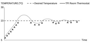
Cooling Mode
Your room thermostat takes the average room temperature of last 40 seconds as basis. With the TPI algorithm in the product by creating a general temperature map of your home, it learns how long it takes to reach the desired room temperature and how this temperature is maintained. Thus, it ensures that the room temperature remains within a certain range.
TPI ROOM THERMOSTAT COOLING MODE WORKING GRAPHIC
WHAT TO KNOW ABOUT TPI ROOM THERMOSTAT
If the placement of the TPI Room Thermostats is changed, the learning process will restart. If the TPI Room Thermostats are de-energized (battery replacement), the learning process will restart. The learning process should be considered as 7 days.
FREQUENTLY ASKED QUESTIONS
- Is my Room Thermostat compatible with my heating/cooling unit?
If your heating / cooling unit has on-off connections, your Room Thermostat is compatible. You can find information about your heating / cooling unit from your heating / cooling unit operating manual or from your heating / cooling unit service.
- How will I connect my Room Thermostat to the heating/cooling unit?
We recommend that the connection between your Room Thermostat and the Heating/Cooling unit should be made by professionally qualified persons.
2×0.75 mm cable is sufficient for the Room Thermostat – heating / cooling unit connection.
Connect one end of the cable pair to the room thermostat connection terminals stated in the user manual of the heating / cooling unit.
Connect the other end of the cable pair to COM and NO inputs of the terminal inside the Wall Hanger of Room Thermostat as shown in the “ROOM THERMOSTAT WIRING DIAGRAM” section.
The direction of the cable ends does not matter.
WARRANTY CONDITIONS
Refer to the warranty conditions in our catalog or production guide currently in force, which can be downloaded from the Imit.it website, or request a copy at info@imit.it