Product description
-
This product is designed according to EN 60730-2-9 and EN60730-2-7, ETSI EN 301 489-1, ETSI EN 300 200-2 standards, in compliance with the applicable EC directives, and made in Italy.
We strictly recommend to install this de-vice according to the safety regulations in force in the European Community and local countries. The mains circuit breaker must be off before carrying out any elec-trical connections.
Technical specifications
-
Power supply 230Vac, 50Hz
Maximum power absorbed < 0,5W
Maintenance of clock in the absence of supply voltage >12h
Maximum capacity of the contacts 5A(1A) 250VAC
Type of action 1B
Operating frequency 868.2 Mhz
Duty cycle of the transmitter < 1%
Capacity 300 m outdoors, 20 m indoors
Type of antenna internal, on PCB
Maximun ambient temperature 50°C
Temperature display range 0°C÷39°C
Temperature regulation range 5°C÷35°C
Temperature resolution 0,1°C
Temperature probe NTC 100KΩ@25°C
Temperature differential from 0,1°C to 2,0°C (std. 0,2°C)
Degree of protection IP20
Insulation class Type II (double insulation)
Pollution degree 2
Software class A
Heat and fire resistance Category D
Storage temperature -25÷60°C
Rated impulse withstand voltage 2,5kV
Installation on wall
External sensor input (optional) NTC 10KΩ@25°C
Installation
-
Place this device far from any heat source or air flow, at about a 1,5mt height from the floor. Open the de-vice pushing the clip on the base right side (Fig.1-A) then rotate the front cover leftward (Fig.1-B) and lift slightly to unfasten it (Fig.1-C).
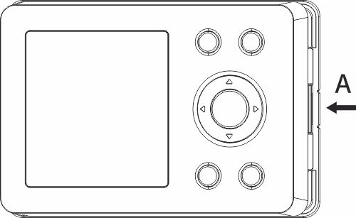
Fig. 1-A 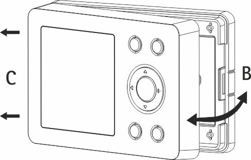
Fig. 1-B, Fig. 1-C Remove the two screws (Fig.2-D) fixing the inner protection cover for the electrical connections. Rotate leftward and release it. Fix the base on to the wall, using the horizontal (Fig.2, A-A or A-B) or the vertical (Fig.2, C-C) holes.
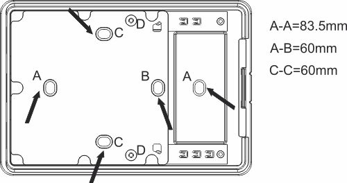
Fig. 2-D
Fig. 2 A-A, A-B
Fig. 2 C-CConnect the wires to the terminal block according to the schematics (Fig.3) and place the protective inner cover again over the electric parts. Fix the screws (Fig.2-D). Dispose the optional external probe cable separately from the relay thermostat connection wires.
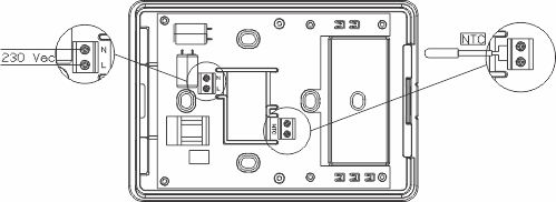
Fig. 3 Close the device proceeding like in Fig.1, reversing the operations order: match the left side of the two parts (Fig.1-C) then rotate the front cover rightward (Fig.1-B) until the clip on the base clacks (Fig.1-A).
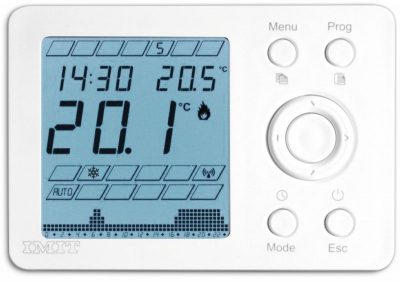
Description of controls and operation
-
Command keys are accomplished on a four position ring each one identified by the arrows


 , an additional key in the middle, hereafter named OK and four keys more: Menu (Copy), Prog (Paste), Mode, Esc. Press the ring exactly on the arrows to avoid multiple keys activations. Press OK key in the middle. Use arrow keys to modify time and temperature values or select the available options. OK key is generally used to confirm the settings.
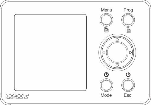
Fig. 4 FIRST START
Setting the clock (Fig.5)
- Set the 24H or 12H by then OK.
- Set the hours by then OK.
- Set the minutes by then OK.
- Set the day of the week by then OK.
Il dispositivo si pone in modo OFF.
The device switches to OFF mode.
Pair with the radio receiver from the installer menu.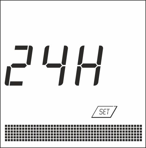
Fig. 5
OFF MODE (Fig.6)
The display shows OFF and the clock, the anti-frost function is active.
Press Mode to browse active modes (Manual Comfort, Manual Economy, Automatic mode). Press Esc to switch between active modes and OFF.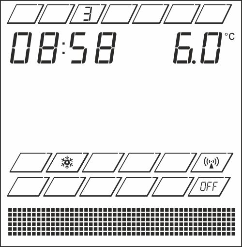
Fig. 6 MANUAL MODE (Fig.7)
Press
or to change and save the temperature set-points:
MAN = Comfort temperature.
MAN ECO = Economy temperature.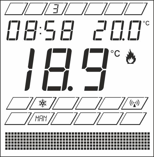
Fig. 7 AUTOMATIC MODE (Fig.8)
The set-point temperature (t1, t2, t3) depends on the saved time program and changes automatically along the day.
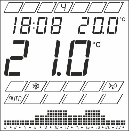
Fig. 8 TIME PROGRAM (Fig.9)
Press Prog, the display shows the set temperature updated at the current half-hour, PROG flashes.
Press OK to select t1, t2 or t3.
Press to select the day of the week.
Press to move along the hours without changing settings.
To make a daily program copy choose the day you want to duplicate and press COPY then move along the week until the desired one and press PASTE.To change the set-point temperatures t1, t2 and t3:
- Press Mode and change the value T1 by .
- Press Mode and change the value T2 by .
- Press Mode and change the value T3 by .
Press Mode to quit and go back to the time program. Press Esc to quit and go back to automatic mode.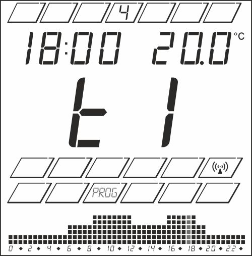
Fig. 9
SEASON MODE: WINTER

Comfort temperature is greater than Economy (t1>t2>t3). When Tamb < Tset heating turns on

SEASON MODE: SUMMER

Comfort temperature is smaller than Economy (t1<t2<t3). When Tamb > Tset cooling turns on

SETTINGS MENU (Fig.10)
Press Menu to enter the settings menu. Press
to browse the available options.- Press to select the season mode (Summer/Winter),
- Press OK to set the clock (like before);
- Press to select (Celsius/Farhenheit) degrees;
- Press to select the language;
- Press to set the desired backlit brightness.
Press Esc to quit the menu.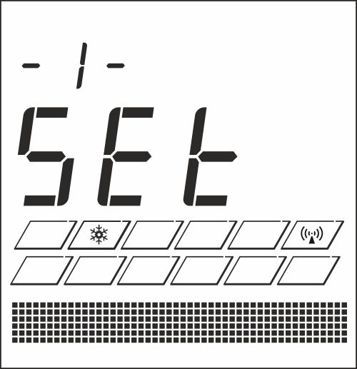
Fig. 10
INSTALLER MENU (Fig.11)
In OFF mode, hold OK for 10 seconds to enter the menu:
Press to browse the available options.- Antifrost = Set antifrost threshold (standard 6.0°C);
- Hysteresis = Switching differential (standard 0.2°C);
- Offset = temperature calibration (standard 0.0°C);
- NTC Internal / NTC External ;
- Hold OK to reset and restore factory settings.
- Confirm with OK to pair the device with the radio receiver and wait for the conclusion of the procedure. If the communication is activated, RADIO OK will appear on the display; otherwise RADIO ERR will appear.
Press Esc to quit the menu.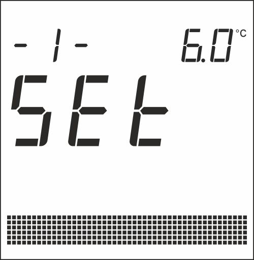
Fig. 11
HUMIDITY DISPLAY OPTION (AVAILABLE ONLY ON WPT VRH MODELS)
In one of the operating modes, press OK to switch between the set temperature or room humidity display in the top right of the screen (Fig.12).
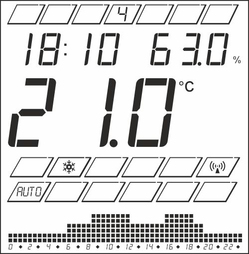
Fig. 12 - Set the 24H or 12H by